01908 6998020845 899 4400 | 01908 699802Tel 01908 699802
What does Duty Cycle mean in Welding

This is a common question. Essentially, Duty Cycle is a measure of how long a welder will operate for before it overheats and cuts out.
As some of you may prefer to watch than read, I’ve also produced a video on this subject
There are 3 key bits of data to Duty Cycle figures:
Amps, a Percentage Figure (%) and the Ambient Temperature the machine was tested in.
Unfortunately, whilst most manufacturers will state the first two figures, they often don’t state what the ambient temperature was when the test was carried out and this is actually a key piece of information! (more on this later).
An example of Duty Cycle data might be:
200amps @ 30% @ 40⁰C
This breaks down as follows:
200amps is what the machine was delivering during the test
30% is the percentage of the work period that the machine continuously delivered 200amps before overheating and cutting out. (in the UK a work period is defined as 10 minutes)
40⁰C (104⁰F) is the ambient temperature of the room when the test was carried out. So the machines fan is cooling the machine with air that is at 40⁰C
What do these Duty Cycle numbers mean?
In our example, the machine delivered 200amps, for 3 minutes (30% of 10 minute work period), in a temperature of 40⁰C, before overheating and cutting out.
Clearly these figures are pretty specific and hardly anyone is ever going to match all the numbers. For example, when is it ever 40⁰C here in the UK???? Clearly if the machine is being used in colder temps, the runtime (%) will increase. Which is why it annoys me that a lot of manufacturers don’t state the ambient temperature the test was conducted in.
Here in Europe, 40⁰C (104⁰F) is the norm, BUT this is not mandatory and some manufacturers will carry out tests in 25⁰C (77⁰F) or even 20⁰C (68⁰F), which, in my view, is a bit naughty because a lower temp will make the % figure look a LOT better than a machine that’s tested in 40⁰C (104⁰F). So beware!!!!!
Conclusion
The point of these numbers is to compare machines. It’s a bit like comparing car fuel consumption, no one ever gets the Miles per Gallon the manufacturers claim the car will do, but you can use the numbers to compare makes/models.
I hope you found this blog article useful, if things work out well for you, please feel free to post some pictures of your achievements on our Facebook Page
Please let me know what you thought of this article by leaving a comment. Don’t worry, your email address won’t be added to a database or shared and you won’t receive any unsolicited email.
Cheers
Graham

Silver Solder & Braze
Silver Solder & Braze are both products used with either an Oxy Acetylene Torch or Oxy Propane Torch.
Silver Solder & Braze, what’s the difference?
For me, the key difference is how they work on the joint.
Silver Solder
Silver Solder is more fluid than Braze and works by being drawn into the joint by a capillary action. So if, for example, you want to join two pieces of thin sheet metal together, you would need to overlap them. The Silver Solder will be drawn through the joint, filling the minute crack between the two pieces of metal, bonding with the surfaces to join them. If you tried to butt the two pieces of metal together, there simply wouldn’t be enough surface area touching to achieve a strong joint.
Silver Solder is used with a Flux, which chemically cleans the metal and keeps it clean during the Silver Soldering process. Silver Solder is also know as Silver Brazing.
Braze
Braze on the other hand, does not get drawn into the joint, but is built up on the surface of the metal being joined, so it looks more like a weld. Like Silver Solder, the Braze material bonds with the surface of the metal being joined.
Braze is used with a Flux, which chemically cleans the metal and keeps it clean during the Brazing process. Brazing is also known as Bronze Welding.
What Silver Solder & Braze have in common is that neither involve melting the metal that’s being joined, that would be welding!
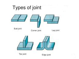
In the joint examples shown, I would use Silver Solder on the Edge & Lap Joint and Braze for the Butt, Corner & Tee Joint.
Types of Silver Solder & Braze
Whilst there are a number of Brazing Alloys on the market, for this article we’ll keep it simple and just cover the most common, C2.
C2 is a multi purpose, Silicon Bronze brazing rod that’s suited to most general purpose brazing on metals including Steel, Copper, Cast Iron and dissimilar metals.
C2 Braze is Brass Coloured and typically melts at around 875⁰C.
Most Silver Solders can be categorised by their Silver content. The Silver content will determine the fluidity and melting temperature, the more Silver, the more fluid and the lower the melting temperature.
Most common are 33% Silver (around 720⁰C), 40% Silver (around 675⁰C) and 55% Silver (around 650⁰C).
Also available are Silver bearing Copper Phosphorus Alloys (CoPhos). These are available with either 2% or 5% Silver and are used primarily for joining Copper to Copper, where, if the metal is clean, no Flux need be used.
Silver Solder can be used to join most common metals, including Mild Steel, Stainless Steel, Copper, Brass, Cast Iron and Dissimilar Metals.
Fluxed or Bare Wire?
Silver Solder & Braze is usually available in 2 or 3 forms:
- Bare Wire – (Silver Solder & Braze). This is my preferred type. With this wire you use a powder flux. This can be coated onto the wire as necessary by gently warming the end of the wire in your flame, then dipping in the powder. This can be repeated as necessary.
- Flux Coated – (Silver Solder & Braze). This may seem like a good idea, but there are, for me, three flaws. Flux coated wires are more expensive than bare wire. If you need additional flux, you’ll still need a pot of powder. If the wires are bent, the flux tends to fall off!
- Flux Impregnated – (Braze Only). Here the flux is in little nicks on the wire. This works very well and the wires can be bent. The downside is that flux impregnated wires are the most expensive.
I hope you found this blog article useful, if things work out well for you, please feel free to post some pictures of your achievements on our Facebook Page
Please let me know what you thought of this article by leaving a comment. Don’t worry, your email address won’t be added to a database or shared and you won’t receive any unsolicited email.
Cheers
Graham
Welding Aluminium
Welding Aluminium has often been seen as a bit of a dark art that’s the preserve of the seasoned professional welder. But is that still the case?
Welding Aluminium is certainly not as straightforward as welding materials like Mild Steel and Stainless Steel, but modern methods and equipment are making the welding of Aluminium less difficult (note I didn’t say easy 🙂
So why is welding aluminium more difficult than other common metals?
Aluminium Properties
Aluminium has an oxide layer on its surface. This oxide layer forms pretty much instantly, so even if you abrade the surface with sandpaper, it reforms before you have a chance to weld.
So a piece of Aluminium can be loosely described as Aluminium, sandwiched between layers of Aluminium Oxide.
Aluminium oxide melts at over 1000⁰C.
Aluminium melts at around 660⁰C.
So here’s the problem when we come to weld your Aluminium melts
- You apply your flame or arc and the job starts to heat up.
- At 660⁰C the Aluminium melts, but you won’t yet have a weld pool because the Aluminium Oxide layer is still in place.
- At a bit over 1000⁰C the Oxide layer melts, but by now the Aluminium is 350⁰C+ ABOVE its melting temperature and so highly fluid and only being held in check by the Oxide layers.
- When the Oxide layers melt, the super melted Aluminium is released and the whole lot falls on the floor, leaving a great big hole!
The solution to the Oxide problem when welding Aluminium depends on the welding process being used.
Gas Welding Aluminium
This involves using a Flux to break down the Aluminium Oxide and prevent it from reforming during the welding process.
Oxy/Acetylene equipment needs to be used (not Oxy/Propane or Propylene).
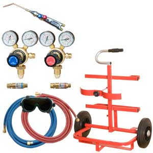
Apart from the use of a flux, Gas Welding Aluminium is much the same in technique terms as Gas Welding Mild Steel. The only real difference is the margin for error, which is almost non existent!
So Gas Welding Aluminium should only really be considered by those with plenty of experience of Gas Welding Steel and a deft hand. But its do-able!!!
If you don’t already have Gas Welding Equipment, we have quite a large range of options for Oxy Acetylene
Tig Welding Aluminium
Tig Welding is the most popular of the processes for Welding Aluminium and is arguably the least difficult.
It’s important to note that Tig Welders fall into two basic categories, those with a Direct Current (DC) output and those with a Direct Current (DC) and Alternating Current (AC) output, generally know as AC/DC Tig Welders.
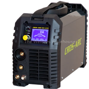
As I’ve already stated, Welding Aluminium requires an AC output, so an AC/DC Tig Welder is what’s needed. We have some separate info about Tig Welders or you can take a look at our range of Tig Welders
Mig Welding Aluminium
Mig can also be used for Welding Aluminium, although the type of Mig Welder you have will be a big factor in how successful you may be.
It’s important to have a Teflon, or Plastic Torch Liner as a steel liner will scrape particles off the surface of the Aluminium Wire, which will quickly cause the wire to jam up in the liner. Ideally, you should also have a ‘U’ shaped feed roller. Most machines are supplied with a ‘V’ shape. You can get away with a ‘V’ shape, but ‘U’ shape will aid reliable feeding.
Pure Argon gas is important, an Argon/Co2 mix will make Welding Aluminium more difficult and may result in poorer weld strength.
Small DIY type machines can be used for Welding Aluminium, but it may be a bit of a challenge as Aluminium requires significantly higher power than steel, so expect Aluminium thickness to be limited to around half the thickness that you machine is capable of in steel.
A good middle of the road option is a machine with at least 200 amps output and a Euro Fitting Torch. Such a machine should have ample power and a Euro type Torch allows a Teflon Liner to be fitted in a couple of minutes.
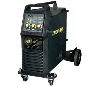
The best type of Mig Welder for welding Aluminium is a Synergic unit that has a dedicated Aluminium program, but these tend to be VERY expensive and therefore more the preserve of businesses with a large scale need for welding Aluminium.
If you don’t already own one, take a look at our range of Mig Welders
In Conclusion
In my opinion, an AC/DC Tig Welder is the best option for most operators wishing to weld Aluminium. AC/DC Tig Welders have come down a lot in price over recent Years and the process is not to intimidating to get the hang of. Having said that, it’s worth buying a machine from a reputable supplier that has good Technical Support available so you have someone to ask for tips along the way.
Gas Welding and Mig Welding Aluminium is also OK, but Gas Welding is, inn my opinion, more difficult and Mig, unless you have industrial equipment, does not produce great quality welds.
I guess the bottom line is it depends what you need to achieve and how much money you want to spend.
Need to Know More?
If you would like to know more, or would like to discuss what equipment might best suit your needs, please don’t hesitate to get in touch, you can write via our Contact Us page, or phone and ask for me! (numbers at the top of this page)
I hope you found this useful, if things work out well for you, please feel free to post some pictures of your achievements on our Facebook Page
Please let me know what you thought of this article by leaving a comment. Don’t worry, your email address won’t be added to a database or shared and you won’t receive any unsolicited email.
Cheers
Graham
Weld Distortion, Causes and Remedies
Weld distortion is the bane of every welders life!
You start out with two beautifully flat pieces of metal, then a few minutes welding later, the shape is more akin to a Donkey’s Hind Leg!!
Believe me, weld distortion is something I have FAR too much experience of 🙂
Back in my Days as a Sheet Metal Worker I had to dress out a LOT of weld distortion. As an Apprentice I HATED the job as I never seemed to get it right, but with time, I learnt the knack. I still hated it 🙂 but got good at sorting it.
Weld Distortion – Causes
Weld distortion has two causes:
- Heat that’s introduced to the job by the welding process. This will vary depending on the welding process used.
- The Weld metal shrinking as it cools.
Lets put a bit more detail on those!
Welding Processes (part 1)
In my experience, by far the worst welding process for introducing heat into the job is Gas Welding, partly because it’s a slow process but mainly because the heat from the flame goes everywhere. Mig Welders and Tig Welders introduce much less heat to the job, despite an arc being far hotter than a flame.
Mig because it’s faster and Tig because it’s more precise about where the heat is focused, ie is where it’s needed.
Reducing Heat Input
There’s not loads you can do about reducing the amount of heat that goes into the job, but here are a few preparitory things you can do that will help.
- Ensure a nice tight joint (unless a gap is necessary for penetration).
- Don’t use excessive power, or move slower than necessary. Clearly you need to uses enough power and move at the right speed for a sound weld, but the objective is not to avoid putting unnecessary heat into the job.
- If possible, place heatsinks (blocks of metal for example), close to each side of the weld. Avoid placing these directly under the joint as this may affect penetration.
Weld Metal Shrinkage
Like most materials, metal expands when it gets hot and shrinks when it cools.
When you produce a weld your putting down Moulten Metal, which will be in an expanded state.
As the weld metal solidifies and cools it contracts, pulling on the metal around it, causing weld distortion.
The easiest way to correct this distortion is to place a solid block of metal behind the weld and gently dress the weld with a Hammer. This will stretch the weld and relieve the pull effect on the surrounding metal. This process should be carried out a little at a time because if you over stretch the weld, you can’t go back and you will still have distortion, only this time caused by a stretched weld rather than a shrunken one!! So be patient, take your time and hammer along the whole weld a little, then repeat as necessary until the distortion is relieved.
Welding Processes (part 2)
The choice of welding process will have an effect on the amount of weld shrink distortion and the ease with which it can be relieved.
Gas Welding and Tig Welding allow the operator better control of the size of the weld. Whilst the weld needs to be big enough to do the job, clearly the bigger the weld the more it will shrink and cause distortion. Mig Welding on the other hand is harder to control when it comes to weld size.
Gas Welding and Tig Welding produce a soft, more malleable weld deposit which is easier to dress, whilst Mig Welding produces a harder weld that can be more prone to cracking when dressed. This hardness is made worse if pure Co2 is used as a shielding gas, so I would alway recommend an Argon/Co2 mix where distortion is likely to be a problem.
If you found this article helpful, you may also find this article on Welding Defects helpful.
Please let me know what you thought of this article by leaving a comment. Don’t worry, your email address won’t be added to a database or shared and you won’t receive any unsolicited email.
Cheers
Graham
Welded Scrap Metal Art
Hi Everyone
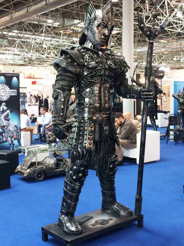
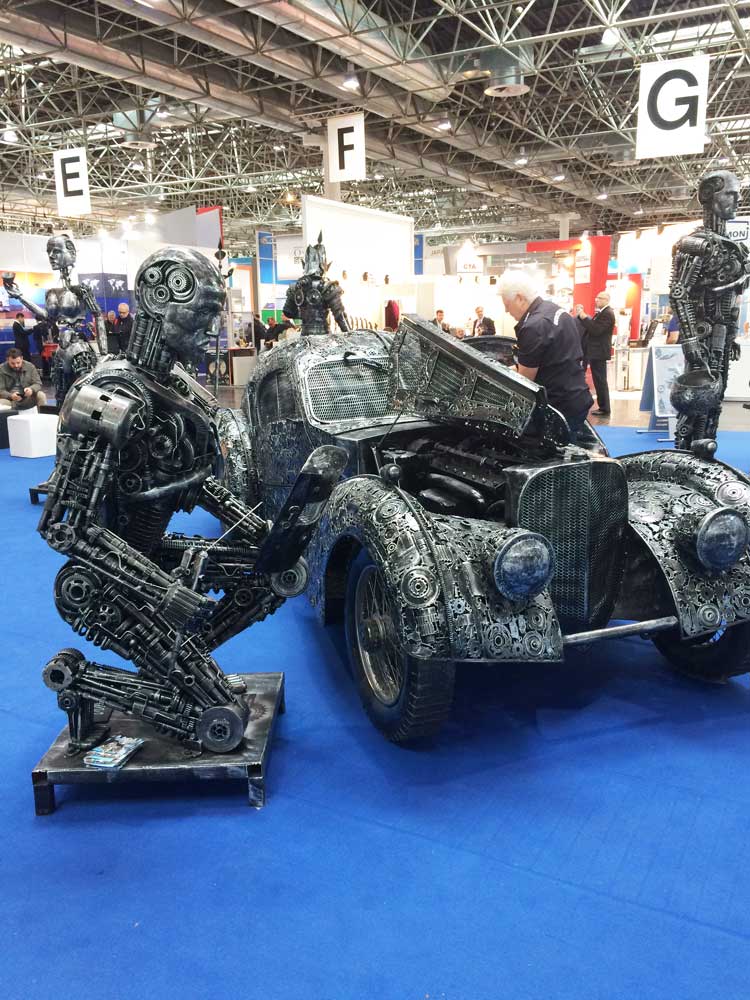
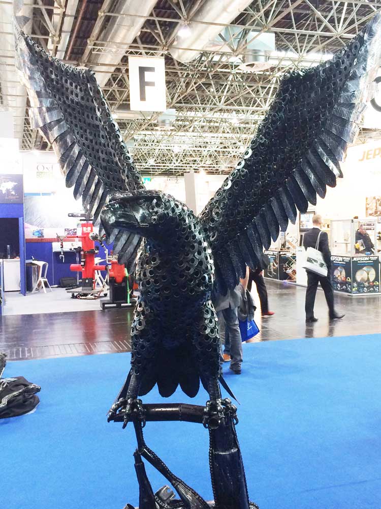
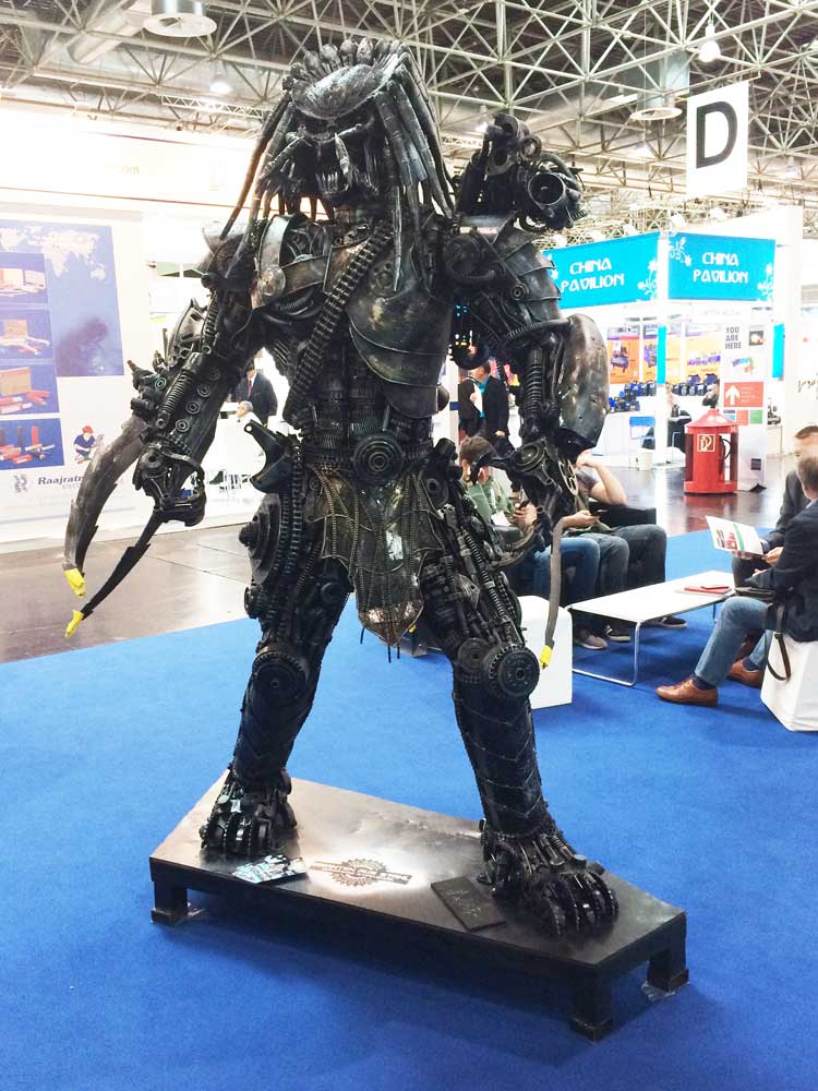
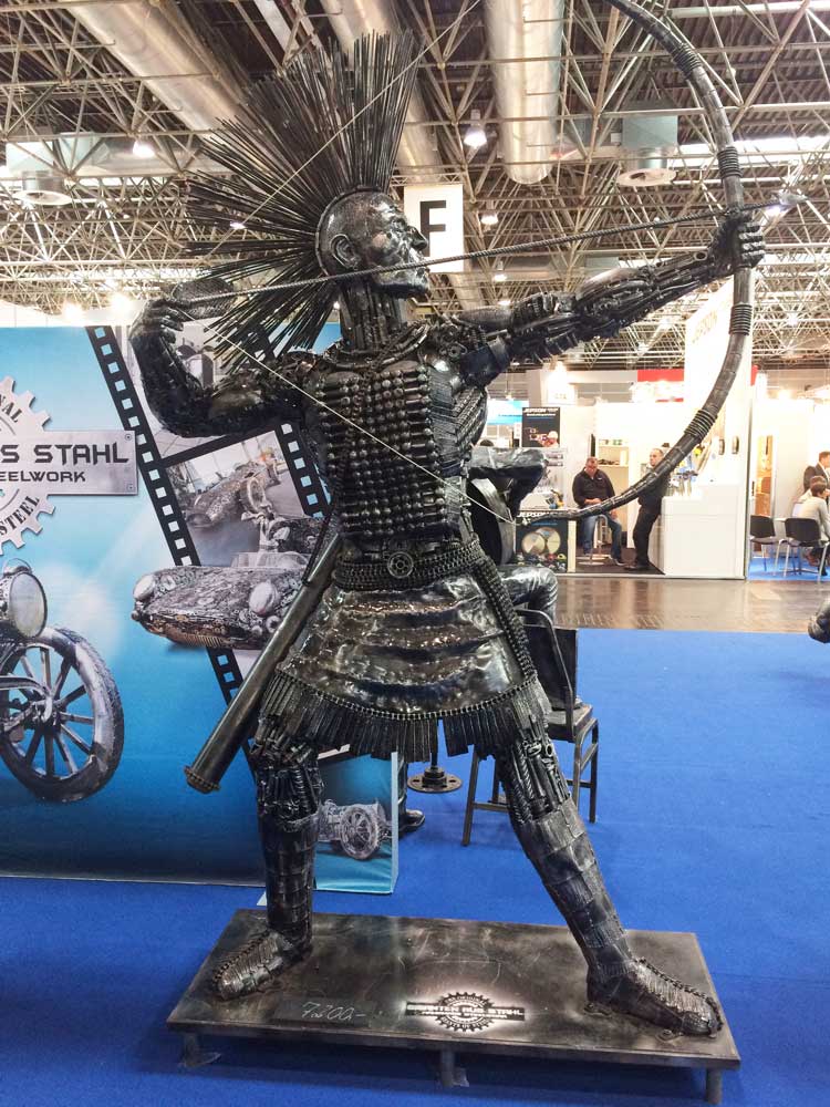
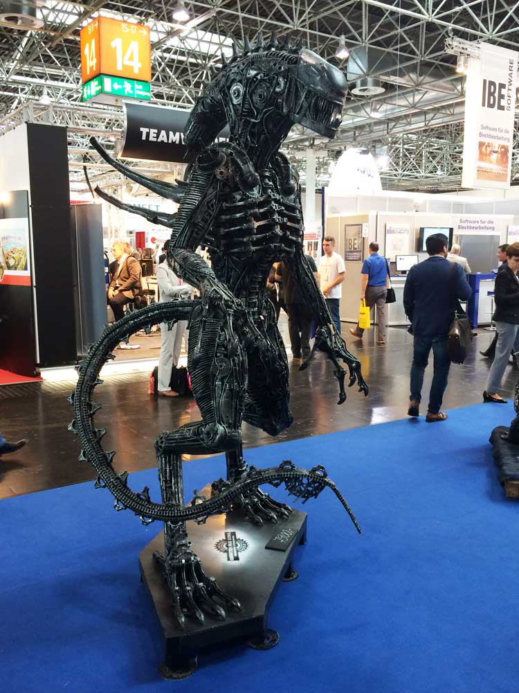
I recently attended an International Welding Expo in Dusseldorf, Germany.
Whilst wandering around I came across an impressive display of Welded Scrap Art.
OK, so most of us would have seen this sort of thing before, but it’s the first time I’ve seen more than one piece in one place. All were made from scrap metal, and old car or motorcycle parts, so as well as being impressive to look at, it struck me a a great way to recycle!
I couldn’t get photos of every item because it was VERY busy with people taking selfies next to them, but I hope you enjoy the photos I did get.
To give you a sense of scale, the 4 figures were all around 7ft/2.2M tall and the car was full size.
Please let me know what you thought of this article by leaving a comment. Don’t worry, your email address won’t be added to a database or shared and you won’t receive any unsolicited email.
Cheers
Graham